Wednesday, October 29, 2008

SAMPLING THEOREM

ANALOG TO DIGITAL CONVERSION

Because of the way computers are organized, signal must be represented by a finite number of bytes. This restriction means that both the time axis and the amplitude axis must be quantized: They must each be a multiple of the integers. 1 Quite surprisingly, the Sampling Theorem allows us to quantize the time axis without error for some signals. The signals that can be sampled without introducing error are interesting, and as described in the next section, we can make a signal "samplable" by filtering. In contrast, no one has found a way of performing the amplitude quantization step without introducing an unrecoverable error. Thus, a signal's value can no longer be any real number. Signals processed by digital computers must be discrete-valued: their values must be proportional to the integers. Consequently, analog-to-digital conversion introduces error.

The Sampling Theorem
Digital transmission of information and digital signal processing all require signals to first be "acquired" by a computer. One of the most amazing and useful results in electrical engineering is that signals can be converted from a function of time into a sequence of numbers without error: We can convert the numbers back into the signal with (theoretically) no error. Harold Nyquist, a Bell Laboratories engineer, first derived this result, known as the Sampling Theorem, in the 1920s. It found no real application back then. Claude Shannon, also at Bell Laboratories, revived the result once computers were made public after World War II.
The sampled version of the analog signal s(t) is s(nTs) where Ts is the SAMPLING INTERVAL
Clearly, the value of the original signal at the sampling times is preserved; the issue is how the signal values between the samples can be reconstructed since they are lost in the sampling process. To characterize sampling, we approximate it as the product x(t)=s(t)Pts(t), with Pts being the periodic pulse signal
the resulting signal as shown in figure below has nonzero values only during the time intervals (nTs-$/2,nTs+$/2) where n is (.....-1,0,1.....)


For our purposes here, we center the periodic pulse signal
about the origin so that its Fourier series coefficients are
real (the signal is even).


If the properties of st s t and the periodic pulse signal are chosen properly, we can recover s(t) from x(t) by filtering.
To understand how signal values between the samples can be "filled" in, we need to calculate the sampled signal's spectrum. Using the Fourier series representation of the periodic sampling signal, eq 3 of above


Considering each term in the sum separately, we need to know the spectrum of the product of the complex exponential and the signal. Evaluating this transform directly is quite easy.


see the bottom equation as above


Thus, the spectrum of the sampled signal consists of weighted (by the coefficients Ck and delayed versions of the signal's spectrum (Figure 2).


In general, the terms in this sum overlap each other in the frequency domain, rendering recovery of the original signal impossible. This unpleasant phenomenon is known as "aliasing".


If, however, we satisfy two conditions:
The signal s(t) is bandlimited—has power in a
restricted frequency range—t0 W Hz, and the sampling interval Ts s small enough so that the individual components in the sum do not overlap Ts<1/2w


aliasing will not occur. In this delightful case, we can recover the original signal by lowpass filtering x(t) with a filter having a cutoff frequency equal to W Hz. These two conditions ensure the ability to recover a bandlimited signal from its sampled version: We thus have the Sampling Theorem.

The frequency 1/2Ts ,
known today as the Nyquist frequency and the Shannon sampling frequency, corresponds to the highest frequency at which a signal can contain energy and remain compatible with the Sampling Theorem. High-quality sampling systems ensure that no aliasing occurs by unceremoniously lowpass filtering the signal (cutoff frequency being slightly lower than the Nyquist frequency) before sampling. Such systems therefore vary the anti-aliasing filter's cutoff frequency as the sampling rate varies. Because such quality features cost money, many sound cards do not have anti-aliasing filters or, for that matter, post-sampling filters. They sample at high frequencies, 44.1 kHz for example, and hope the signal contains no frequencies above the Nyquist frequency (22.05 kHz in our example). If, however, the signal contains frequencies beyond the sound card's Nyquist frequency, the resulting aliasing can be impossible to remove.

If we satisfy the Sampling Theorem's conditions, the signal will change only slightly during each pulse. As we narrow the pulse, making Δ Δ smaller and smaller, the nonzero values of the signal s(t) pTs(t)will simply be s (nTs) , the signal's samples. If indeed the Nyquist frequency equals the signal's highest frequency, at least two samples will occur within the period of the signal's highest frequency sinusoid. In these ways, the sampling signal captures the sampled signal's temporal variations in a way that leaves all the original signal's structure intact.

Monday, October 20, 2008

PRPERTIES OF AUTOCORELATION FUNCTION(KAUNDINYA

DEFINITION:

The expected value of the product of a random variable or signal realization with a time-shifted version of itself


With a simple calculation and analysis of the autocorrelation function, we can discover a few important characteristics about our random process. These include:

1)How quickly our random signal or processes changes with respect to the time function

2)Whether our process has a periodic component and what the expected frequency might be

As was mentioned above, the autocorrelation function is simply the expected value of a product. Assume we have a pair of random variables from the same process, X 1 =X (t 1)and X 2 =X (t 2) , then the autocorrelation is often written as


The above equation is valid for stationary and nonstationary random processes. For stationary processes, we can generalize this expression a little further. Given a wide-sense stationary processes, it can be proven that the expected values from our random process will be independent of the origin of our time function. Therefore, we can say that our autocorrelation function will depend on the time difference and not some absolute time. For this discussion, we will let τ= t 2 - t 1 , and thus we generalize our autocorrelation expression as

WHAT IS AUTOCORRELATION?(KAUNDINYA)

Correlation is a mathematical tool used frequently in signal processing for analysing functions or series of values, such as time domain signals (Wikipedia 2006). Correlation is the mutual relationship between two or more random variables (Ali). Autocorrelation is the correlation of a signal with itself (Parr 1999). This is unlike cross-correlation, which is the correlation of two different signals (Parr 1999).

Autocorrelation is useful for finding repeating patterns in a signal, such as determining the presence of a periodic signal which has been buried under noise, or identifying the fundamental frequency of a signal which doesn't actually contain that frequency component, but implies it with many harmonic frequencies (Wikipedia 2006).

Different definitions of autocorrelation are in use depending on the field of study which is being considered and not all of them are equivalent (Wikipedia 2006). In some fields, the term is used interchangeably with autocovariance(Wikipedia 2006).

In statistics, the autocorrelation of a discrete time series or a process Xt is simply the correlation of the process against a time-shifted version of itself (Wikipedia 2006). If Xt is second-order stationary with mean μ then this definition is


where E is the expected value and k is the time shift being considered (usually referred to as the lag) (Wikipedia 2006). This function has the attractive property of being in the range [−1, 1] with 1 indicating perfect correlation (the signals exactly overlap when time shifted by k) and −1 indicating perfect anti-correlation (Wikipedia 2006). It is common practice in many disciplines to drop the normalisation by σ2 and use the term autocorrelation interchangeably with autocovariance (Wikipedia 20006).

In signal processing, given a signal f(t), the continuous autocorrelation Rf(τ) is the continuous cross-correlation of f(t) with itself, at lag τ, and is defined as:

Saturday, October 18, 2008

CONVOLUTION EXAMPLE(DISCUSSED IN SS CLASS BY KAUNDINYA)

Convolve together two square pulses, xtxt and htht, as shown in Figure


Two basic signals that we will convolve together.

Reflect and Shift
Now we will take one of the functions and reflect it around the y-axis. Then we must shift the function, such that the origin, the point of the function that was originally on the origin, is labeled as point t. This step is shown in Figure,
h(t-τ).
Reflected square pulse.
Reflected and shifted square pulse.
h(-τ)and h(t-τ)
Note that in the above Figure ττ is the 1st axis variable while tt is a constant (in this figure). Since convolution is commutative it will never matter which function is reflected and shifted; however, as the functions become more complicated reflecting and shifting the "right one" will often make the problem much easier.

Regions of Integration
We start out with the convolution integral The value of the function y at time t is given by the amount of overlap(to be precise the integral of the overlapping region) between h(t-τ) and x(τ) .
Next, we want to look at the functions and divide the span of the functions into different limits of integration. These different regions can be understood by thinking about how we slide h(t-τ) over x(τ) see Figure 3.


In this case we will have the following four regions. Compare these limits of integration to the four illustrations of h(t-τ) and x(τ)in Figure 3.


Four Limits of Integration

Using the Convolution Integral
Finally we are ready for a little math. Using the convolution integral, let us integrate the product of x h(t-τ) x(τ) . For our first and fourth region this will be trivial as it will always be 0. The second region, 0≤t<1>

Convolution Results


common sense aproach
By looking at Figure we can obtain the system output, ytyt, by "common" sense. For
t<0 there is no overlap, so y(t) is 0. As tt goes from 0 to 1 the overlap will linearly increase with a maximum for t=1, the maximum corresponds to the peak value in the triangular pulse. As tt goes from 1 to 2 the overlap will linearly decrease. For t>2 there will be no overlap and hence no output.

We see readily from the "common" sense approach that the output function y(t) is the same as obtained above with calculations. When convolving to square pulses the result will always be a triangular pulse. Its origin, peak value and strech will, of course, vary.

Traditional Day

MRITS is organising the Traditional Day on 20th of this October.All are hereby informed that every one should come to college in a traditional look.Several cultural programmes will conducted on that day and students who are interested can participate.Some competitions are also being organised.All will be encouraged to participate in the program.Its a kind of interaction for the juniors with the seniors and we hope that its going to be a big hit.

MRITS - Blood Donation Camp

The NSS unit of Mallareddy institute of technology and sciences in association with the red cross society organised a blood donation camp on the 18th of october .Under the careful guidance of the NSS unit chief Mr venkatarmana ,a total of 102 volunteers worked together to make this donation camp a very fruitful one.The red cross team which visited the college was headed by the very able Dr Yamadharma and other 12 asst doctors who were very efficient and careful about their work and also helped at putting the donors at ease.The camp consisted of 12 beds,a relaxation area for the donors where they were provided with food and energy drinks and a waiting hall for the donors.The camp which started at 10 in the morning and continued upto 4 in the evening got a very good response from the students and lecturers of different colleges,recording upto 300 registrations and 253 donations in all.The chairman of mallareddy group of institutions,Mallareddy garu,visited the camp and appreciated the initiative taken by the NSS group.Dr K Ravindra,principal of Mrits visited the camp thrice and made sure that every was smooth sailing.All the NSS volunteers worked tirelessly,from guiding the donors on what to do to giving them moral support,to make sure that none would face any kind of inconvenience.The red cross team said that this camp was a well organised one with total coordination between the doctors and the volunteers,and all this coudlnt have been done without the NSS unit.Taking the success of this camp as an inspiration the NSS unit of MRITS is organising an eye donation camp very soon.

Friday, October 17, 2008

Red Hat !


by Terry Collings, Kurt Wall
Paperback: 1000 pages
Publisher: Red Hat; (January 01, 2002)
Language: English
ISBN: 076453632X
Format: PDF

This book is the book you need to run your business with Red Hat. It provides comprehensive coverage on how to manage and network the Red Hat Linux OS and step-by-step instructions needed to maintain and/or add to the Red Hat Linux system.

This book features an entire part on security and problem solving that covers detecting intrusions/*******, implementing local security, firewalls, and Internet security. Other topics include: RAID; TCP/IP networking; connecting to Microsoft networks; connecting to Apple networks; the Red Hat network; upgrading and customizing the kernel; using scripts; backing up and restoring the file system.

Download Link:

http://rapidshare.com/files/13528848/b0483.rar.html

Wednesday, October 15, 2008

MRITS - Blood Donation

The NSS unit of our college (MRITS),launched to serve the people has decided to organise a blood donation camp this saturday(18th oct).It would be held in the college premises and the programme commences at 10:00 am.The principals of all the colleges of MRGI Group are invited along with their faculty and students.Mr.Venkataramana,Cheif of NSS Unit MRITS,announced that this is the first programme being organised by NSS Unit and would try to make it a success with the help of volunteers and all the students.He also said that the programmes is being organised in association with RED CROSS SOCIETY and medical assistance will be given by them to all.
All the volunteers are taking care of the arrangements and every minute step is being taken to see that no problems will be faced by anyone.All the faculty and students of all colleges and all the outsiders are also allowed to participate in the donation.Infact ALL ARE INVITED.

Tuesday, October 14, 2008

Biasing (electronics)

Biasing in electronics is the method of establishing predetermined voltages and/or currents at various points of a circuit to set an appropriate operating point.

The operating point of a device, also known as bias point or quiescent point (or simply Q-point), is the DC voltage and/or current which, when applied to a device, causes it to operate in a certain desired fashion. The term is normally used in connection with devices such as transistors and diodes which ar

Importance in linear circuits

Linear circuits involving transistors typically require specific DC voltages and currents to operate correctly, which can be achieved using a biasing circuit.

As an example of the need for careful biasing, consider a transistor amplifier. In linear amplifiers, a small input signal gives larger output signal without any change in shape (low distortion): the input signal causes the output signal to vary up and down about the Q-point in a manner strictly proportional to the input. However, because a transistor is nonlinear, the transistor amplifier only approximates linear operation. For low distortion, the transistor must be biased so the output signal swing does not drive the transistor into a region of extremely nonlinear operation. For a bipolar transistor amplifier, this requirement means that the transistor must stay in the active mode, and avoid cut-off or saturation. The same requirement applies to a MOSFET amplifier, although the terminology differs a little: the MOSFET must stay in the active mode (or saturation mode), and avoid cut-off or Ohmic operation (or triode mode).

Bipolar junction transistors

For bipolar junction transistors the bias point is chosen to keep the transistor operating in the active mode, using a variety of circuit techniques, establishing the Q-point DC voltage and current. A small signal is then applied on top of the Q-point bias voltage, thereby either modulating or switching the current, depending on the purpose of the circuit.

The quiescent point of operation is typically near the middle of DC load line. The process of obtaining certain DC collector current at a certain DC collector voltage by setting up operating point is called biasing.

After establishing the operating point, when input signal is applied, the output signal should not move the transistor either to saturation or to cut-off. However, this unwanted shift might occur due to various reasons outlined below:

To avoid a shift of Q-point, bias-stabilization is necessary. Various biasing circuits can be used for this purpose.

Types of bias circuit

The following discussion treats five common biasing circuits used with bipolar transistors:

  1. Fixed bias
  2. Collector-to-base bias
  3. Fixed bias with emitter resistor
  4. Voltage divider bias

Types of bias circuit

The following discussion treats five common biasing circuits used with bipolar transistors:

  1. Fixed bias
  2. Collector-to-base bias
  3. Fixed bias with emitter resistor
  4. Voltage divider bias
  5. Emitter bias

15 tried-and-tested methods for Global Warming Solutions

We are living in modernized world and we have lots resources and technologies to reduce the threat of global warming. Global Warming Solutions are always available that will give boost to International economy by creating various jobs, saving consumers money, and protecting our national security. If we invest in renewable energy and energy efficiency programs, than we can have better day tomorrow. Increasing the efficiency of the cars we drive, we can take essential steps toward reducing our dependence on oil and other fossil fuels that cause global warming for most than ever.

1. Start burying stuff on a massive scale
The whole problem with global warming starts with digging up and burning the carbon from plants and animals, in the form of coal and oil, that has been buried for millions of years. So two German scientists have a solution: Start burying stuff on a massive scale.
2. Use Energy efficient home appliances
Every single Individual can make big differences which will in turn give a impact on global climate change in a positive or negative way. Your family and you don't have to stop using heat-trapping emitting products like appliances, industrial equipment and buildings for reducing global warming level, but making clever choices to select energy-efficient products for your use, Which might cost you more than usual, but often it will pay back you into the form of energy savings within a couple of years. Most of us have bought an Energy Star appliance or two, and have seen firsthand how much money and energy they can save.
3. Plant 3.8 million square miles of forest every year
One of the most important global warming solution is plant 3.8 million square miles of forest every year to counteract current global carbon dioxide emissions.
4. Unplug appliances which is not in use
Unplug seldom-used appliances, like an extra refrigerator, A/C, cooler etc which you doesn't use frequently.
5. Unplug your charger
Unplug your chargers when you're not charging any pda's, cell phones, digital cameras and other gadgets.
6. Switch off T.V. and home theater from power strips
Switch off televisions, home theater equipment, and stereos by using power strips When it is ideal(not in use).
7. Keep your computer on sleep and hibernate mode
Set your computer to "sleep mode" feature, Which enables your computer to use very much less power as compared to usual it takes. Hibernating computers can make you able to save more energy than enabling your computer to sleep mode as it shuts down your computer by saving your work at the same state.
8. Put lights off when not in use
Don't forget to putt off the switch of lights when you leave a room. Practice the same in your offices/workplaces.
9. Use Energy Star compact fluorescents
Don't use any bulbs which require high energy, there is a solution for this use Energy Star compact fluorescents, which have been concluded that it is best for quality and longevity. If you swap the five standard light bulbs you use most for energy-saving compact fluorescents, you can save roughly $60 each year on electricity.
10. Change Air filters on timely basis
By changing air filters and keeping air conditioner coils clean can decrease emission of co2 in Air.
11. Use Renewable power resources(if applicable)
Now it is permissible to use the power to choose their own energy supplier for any consumer. If it is applicable in your selected area or sector, Select a supplier who uses renewable power resources, like solar, wind, low-impact hydroelectric, or geothermal to generate energy(electricity).
12. Keep the tires on your car adequately expanded
You might be driving you car with out taking care of your vehicle Tires. You have to Keep the tires on your car adequately expanded(inflated) and so u can save lots of carbon-di-oxide as well as wealth.
13. Use Hybrid and Fuel Efficient Car
Buy Hybrid Car and Fuel Efficient Car which can increase your fuel efficiencies. Will decrease level of CO2 and the most important thing your wealth.
14. Avoid eating of chemically produced foods
Don't eat chemically produced foods which is produced in the modern agriculture world now. This kind of food pollute the water supply and require energy to produce while productions.
15. Increase the usage of Recyclable products
Use Recycled products and goods such as papers, plastic bags and other related stuffs.

SINGLE –STAGE BJT AMPLIFIER CONFIGURATIONS

Three different amplifier circuit configurations can be obtained by selecting one of the transistor terminals as a common between input circuit and output circuit. In the BJT circuits, figure 3 shows these configurations, which are known as Common Base (CB), Common Emitter (CE), and Common Collector (CC). These amplifier circuit configurations lead to significant changes in the amplifier characteristics. The most noticeable changes in CC (emitter follower) configurations are: the input resistance becomes very high and the gain is close to the unity. These specific characteristics are translated into a useful application known as buffer amplifier.


Figure 1

Therefore amplifier configurations are employed to widen the scope of the amplifier circuit applications. Table1 summarizes the main characteristics of each configuration. The model used in the analysis is the T-model with transistor parameters, : transconductance, : emitter resistance, : common-emitter current gain, and : common-base current gain. , , are the collector, the emitter, and the load resistors NOTICE THAT in CE configuration the presence of has a very large impact on the input resistance and the voltage gain. Most device manufacturers specify as and as . From table1 we observe that the input resistance of the CB configuration is much smaller than the input resistance of CE or CC configuration. The input and output resistances of the above amplifier configurations limit the use of the amplifier to certain applications. Figure 2 below shows a single stage CE and CB amplifiers. Notice the difference between the relative positions of the input-output signals in both configurations.

GAUTAM KAUNDINYA AND SURYA TEJ REDDY

Both of these are the students of MRITS-2007 batch studying ECE .They started blogging almost together with mritsece.blogspot.com.From then onwards they have been experimenting on blogging.At the early stages they gone through very difficult times in knowing about blogging
and to make it really academic and useful so that they can create a history.


Surya mainly handled the display and lookout and Gautam's job was to take care of posts nad information both had a tough time for learning& searching.
At the midst they had some arguements after which they brokeout and started to compete with each other there by growing better and better.They were not able to concentrate on studies properly because of the hunger of growing large.Even if they were exams they did not leave blogging.Of course it affected their marks,they both secured 70% and 67% in their first year.
When the second year started they began to concentrate on studies for scoring.You know that it was the decision made under pressure.When they felt relieved of the pressure they made up each other for working as team better than everbefore.So they created this blog which has a better outlook than any of their earlier blogs and the main site
Now as u all can see what has been the progress till now......tommorow....ever....

Monday, October 13, 2008

Emitter Follower Discussion


The common collector junction transistor amplifier is commonly called an emitter follower. The voltage gain of an emitter follower is just a little less than one since the emitter voltage is constrained at the diode drop of about 0.6 volts below the base . Its function is not voltage gain but current or power gain and impedance matching. It's input impedance is much higher than its output impedance so that a signal source does not have to work so hard. This can be seen from the fact that the base current in on the order of 100 times less that the emitter current. The low output impedance of the emitter follower matches a low impedance load and buffers the signal source from that low impedance.

Bridge Rectifier

A diode bridge or bridge rectifier is an arrangement of four diodes in a bridge configuration that provides the same polarity of output voltage for any polarity of input voltage. When used in its most common application, for conversion of alternating current (AC) input into direct current (DC) output, it is known as a bridge rectifier. A bridge rectifier provides full-wave rectification from a two-wire AC input, resulting in lower cost and weight as compared to a center-tapped transformer design, but has two diode drops rather than one, thus exhibiting reduced efficiency over a center-tapped design for the same output voltage.

Sunday, October 12, 2008

CLASS A AMPLIFIER

100% of the input signal is used (conduction angle Θ = 360° or 2π, i.e. the active element works in its linear range all of the time). Where efficiency is not a consideration, most small signal linear amplifiers are designed as Class A, which means that the output devices are always in the conduction region. Class A amplifiers are typically more linear and less complex than other types, but are very inefficient. This type of amplifier is most commonly used in small-signal stages or for low-power applications (such as driving headphones).

Class A amplifying devices operate over the whole of the input cycle such that the output signal is an exact scaled-up replica of the input with no clipping. Class A amplifiers are the usual means of implementing small-signal amplifiers. They are not very efficient;

a theoretical maximum of 50% is obtainable with inductive output coupling and only 25% with capacitive coupling.


In a Class A circuit, the amplifying element is biased so the device is always conducting to some extent, and is operated over the most linear portion of its characteristic curve (known as its transfer characteristic or transconductance curve). Because the device is always conducting, even if there is no input at all, power is drawn from the power supply. This is the chief reason for its inefficiency.

high output powers are needed from a Class A circuit, the power waste (and the accompanying heat) will become significant. For every watt delivered to the load, the amplifier itself will, at best, dissipate another watt. For large powers this means very large and expensive power supplies and heat sinking. Class A designs have largely been superseded for audio power amplifiers, though some audiophiles believe that Class A gives the best sound quality, due to it being operated in as linear a manner as possible which provides a small market for expensive high fidelity Class A amps. In addition, some aficionados prefer thermionic valve (or "tube") designs instead of transistors, for several claimed reasons:

Tubes are more commonly used in class A designs, which have an asymmetrical transfer function. This means that distortion of a sine wave creates both odd- and even-numbered harmonics. The claim is that this sounds more "musical" than the higher level of odd harmonics produced by a symmetrical push–pull amplifier. Though good amplifier design can reduce harmonic distortion patterns to almost nothing, distortion is essential to the sound of electric guitar amplifiers, for example, and is held by recording engineers to offer more flattering microphones and to enhance "clinical-sounding" digital technology.

If Valves use many more electrons at once than a transistor, and so statistical effects lead to a "smoother" approximation of the true waveform — see shot noise for more on this. Junction field-effect transistors (JFETs) have similar characteristics to valves, so these are found more often in high quality amplifiers than bipolar transistors. Historically, valve amplifiers often used a Class A power amplifier simply because valves are large and expensive; many Class A designs use only a single device.

Transistors are much cheaper, and so more elaborate designs that give greater efficiency but use more parts are still cost-effective. A classic application for a pair of class A devices is the long-tailed pair, which is exceptionally linear, and forms the basis of many more complex circuits, including many audio amplifiers and almost all op-amps. Class A amplifiers are often used in output stages of op-amps; they are sometimes used as medium-power, low-efficiency, and high-cost audio amplifiers. The power consumption is unrelated to the output power. At idle (no input), the power consumption is essentially the same as at high output volume. The result is low efficiency and high heat dissipation.

Thursday, October 9, 2008

types of dc machines

We are Independent!


Happy Dussehra!


We have come across people of different sorts!
We have come across people who bank on ones efforts!
We have faced betrayals!
So,we chose to be independent!

We are not a part of anything!

We don't want to be a part of something!

We have set standards!
And people are following it!

We are technical!

We are not after publicity!
The students are with us!

and,We are
MRITS ECE
mritsece.co.nr
by the students,with the faculty and for the students

Tuesday, October 7, 2008

THE TRANSISTOR AS A SWITCH

Because a transistor's collector current is proportionally limited by its base current, it can be used as a sort of current-controlled switch. A relatively small flow of electrons sent through the base of the transistor has the ability to exert control over a much larger flow of electrons through the collector.

Suppose we had a lamp that we wanted to turn on and off by means of a switch. Such a circuit would be extremely simple:

For the sake of illustration, let's insert a transistor in place of the switch to show how it can control the flow of electrons through the lamp. Remember that the controlled current through a transistor must go between collector and emitter. Since its the current through the lamp that we want to control, we must position the collector and emitter of our transistor where the two contacts of the switch are now. We must also make sure that the lamp's current will move against the direction of the emitter arrow symbol to ensure that the transistor's junction bias will be correct:

In this example I happened to choose an NPN transistor. A PNP transistor could also have been chosen for the job, and its application would look like this

The choice between NPN and PNP is really arbitrary. All that matters is that the proper current directions are maintained for the sake of correct junction biasing (electron flow going against the transistor symbol's arrow).

Going back to the NPN transistor in our example circuit, we are faced with the need to add something more so that we can have base current. Without a connection to the base wire of the transistor, base current will be zero, and the transistor cannot turn on, resulting in a lamp that is always off. Remember that for an NPN transistor, base current must consist of electrons flowing from emitter to base (against the emitter arrow symbol, just like the lamp current). Perhaps the simplest thing to do would be to connect a switch between the base and collector wires of the transistor like this:

If the switch is open, the base wire of the transistor will be left "floating" (not connected to anything) and there will be no current through it. In this state, the transistor is said to be cutoff. If the switch is closed, however, electrons will be able to flow from the emitter through to the base of the transistor, through the switch and up to the left side of the lamp, back to the positive side of the battery. This base current will enable a much larger flow of electrons from the emitter through to the collector, thus lighting up the lamp. In this state of maximum circuit current, the transistor is said to be saturated.

Of course, it may seem pointless to use a transistor in this capacity to control the lamp. After all, we're still using a switch in the circuit, aren't we? If we're still using a switch to control the lamp -- if only indirectly -- then what's the point of having a transistor to control the current? Why not just go back to our original circuit and use the switch directly to control the lamp current?

There are a couple of points to be made here, actually. First is the fact that when used in this manner, the switch contacts need only handle what little base current is necessary to turn the transistor on, while the transistor itself handles the majority of the lamp's current. This may be an important advantage if the switch has a low current rating: a small switch may be used to control a relatively high-current load. Perhaps more importantly, though, is the fact that the current-controlling behavior of the transistor enables us to use something completely different to turn the lamp on or off. Consider this example, where a solar cell is used to control the transistor, which in turn controls the lamp:

Or, we could use a thermocouple to provide the necessary base current to turn the transistor on:

Even a microphone of sufficient voltage and current output could be used to turn the transistor on, provided its output is rectified from AC to DC so that the emitter-base PN junction within the transistor will always be forward-biased
IMG SRC="http://sub.allaboutcircuits.com/images/03081.png">
The point should be quite apparent by now: any sufficient source of DC current may be used to turn the transistor on, and that source of current need only be a fraction of the amount of current needed to energize the lamp. Here we see the transistor functioning not only as a switch, but as a true amplifier: using a relatively low-power signal to control a relatively large amount of power. Please note that the actual power for lighting up the lamp comes from the battery to the right of the schematic. It is not as though the small signal current from the solar cell, thermocouple, or microphone is being magically transformed into a greater amount of power. Rather, those small power sources are simply controlling the battery's power to light up the lamp.

IMPORTANT NOTES


-Transistors may be used as switching elements to control DC power to a load. The switched (controlled) current goes between emitter and collector, while the controlling current goes between emitter and base
-When a transistor has zero current through it, it is said to be in a state of cutoff (fully nonconducting).
-When a transistor has maximum current through it, it is said to be in a state of saturation (fully conducting).

Monday, October 6, 2008

USES OF AMPLIFIERS IN AUDIO SYSTEM

At the most basic level, a signal amplifier does exactly what you expect – it makes a signal bigger! However the way in which this is done does vary with the design of the actual amplifier, the type of signal, and the reason why we’re wanting to enlarge the signal. We can illustrate this by considering the common example of a ‘Hi-Fi’ audio system.

In a typical modern hi-fi system, the signals will come from a unit like a CD Player, FM Tuner, or a Tape/MiniDisc unit. The signals these produce have typical levels of the order of 100mV or so when the music is moderately loud. This is a reasonably large voltage, easy to detect with something like an oscilloscope or a voltmeter. However the actual power levels of these signals is quite modest. Typically, these sources can only provide currents of a few milliamps, which by means powers of just a few milliwatts. A typical loudspeaker will require between a few Watts and perhaps over 100 Watts to produce loud sounds. Hence we will require some form of Power Amplifier to ‘boost’ the signal power level from the source and make it big enough to play the music.

We usually want to be able to control the actual volume – e.g. turn it up to annoy neighbours, or down to chat to someone. This means we have to have some way of adjusting the overall Gain of the system. We also want other functions – the most obvious being to select which signal source we wish to listen to. Sometimes all these functions are built into the same piece of equipment, however is often better to use a separate box which acts as a Pre-Amp to select inputs, adjust the volume, etc. In fact, even when built into the same box, most amplifier systems use a series of ‘stages’ which share the task of boosting and controlling the signals.

The system shown in figure 1.2 is similar to the previous arrangement, but in this case is used for taking signals from microphones and ‘mixing’ them together to produce a combined output for power amplification. This system also include an ‘EQ’ unit (Equalising) which is used to adjust and control the frequency response.

Microphones tend to produce very small signal levels. typically of the order of 1 mVrms or less, with currents of a few tens of microamps or less – i.e. signal powers of microwatts to nanowatts. This is similar to many other forms of sensor employed by scientists and engineers to measure various quantities. It is usual for sensors to produce low signal power levels. So low, in fact, that detection and measurement can be difficult due to the presence of Noise which arises in all electronic system. For that reason it is a good idea to amplify these weak, sensor created, signals, as soon as possible to overcome noise problems and give the signal enough energy to be able to travel along the cables from the source to its destination. So, as shown in figure 1.2, in most studios, the microphone sensor will actually include (or be followed immediately) by a small Low-Noise Amplifier (LNA).

Due to the range of tasks, amplifiers tend to be divided into various types and classes. Frequently a system will contain a combination of these to achieve the overall result. Most practical systems make use of combinations of standard ‘building block’ elements which we can think of as being the ‘words’ of the language of electronics

Sunday, October 5, 2008

Vishnu sir said.....


Complex numbers are used a great deal in electronics. The main reason for this is they make the whole topic of analyzing and understanding alternating signals much easier. This seems odd at first, as the concept of using a mix of real and 'imaginary' numbers to explain things in the real world seem crazy! Once you get used to them, however, they do make a lot of things clearer. The problem is understanding what they 'mean' and how to use them in the first place. To help you get a clear picture of how they're used and what they mean we can look at a mechanical example...

The above animation shows a rotating wheel. On the wheel there is a blue blob which goes round and round. When viewed 'flat on' we can see that the blob is moving around in a circle at a steady (if you computer is working OK!) rate. However, if we look at the wheel from the side we get a very different picture. From the side the blob seems to be oscillating up and down. If we plot a graph of the blob's position (viewed from the side) against time we find that it traces out a sinewave shape which oscillates through one cycle each time the wheel completes a rotation. Here, the sine-wave behaviour we see when looking from the side 'hides' the underlaying behaviour which is a continuous rotation.

We can now reverse the above argument when considering a.c. (sinewave) oscillations in electronic circuits. Here we can regard the oscillating voltages and currents as 'side views' of something which is actually 'rotating' at a steady rate. We can only see the 'real' part of this, of course, so we have to 'imagine' the changes in the other direction. This leads us to the idea that what the oscillation voltage or current that we see is just the 'real' portion' of a 'complex' quantity that also has an 'imaginary' part. At any instant what we see is determined by a phase angle which varies smoothly with time


The smooth rotation 'hidden' by our sideways view means that this phase angle varies at a steady rate which we can represent in terms of the signal frequency, 'f'. The complete complex version of the signal has two parts which we can add together provided we remember to label the imaginary part with an 'i' or 'j' to remind us that it is imaginary. Note that, as so often in science and engineering, there are various ways to represent the quantities we're talking about here. For example: Engineers use a 'j' to indicate the square root of minus one since they tend to use 'i' as a current. Mathematicians use 'i' for this since they don't know a current from a hole in the ground! Similarly, you'll sometimes see the signal written as an exponential of an imaginary number, sometimes as a sum of a cosine and a sine. Sometimes the sign on the imaginary part may be negative. These are all slightly different conventions for representing the same things. (A bit like the way 'conventional' current and the actual electron flow go in opposite directions) The choice doesn't matter so long as you're consistent during a specific argument.

We can now consider oscillating currents and voltages as being complex values that have a real part we can measure and an imaginary part which we can't. At first it seems pointless to create something we can't see or measure, but it turns out to be useful in a number of ways.

Firstly, it helps us understand the behaviour of circuits which contain reactance (produced by capacitors or inductors) when we apply a.c. signals. Secondly, it gives us a new way to think about oscillations. This is useful when we want to apply concepts like the conservation of energy to understanding the behaviour of systems which range from simple a mechanical pendulums to a quartz-crystal oscillator.

CHECK OUT THE AMAZING ANIMATION EXPLAINATION TO THE OPERATIONAL AMPLIFIERS

THE LINK BELOW IS ANIMATION FROM ARIZONA STATE UNIVERSITY.

I AM SURE THAT ALL YOUR DOUBTS ABOUT OP-AMPS WILL BE CLEARED OUT.


THE AMAZING ANIMATION OF OPERATIONAL AMPLIFIERS 
HELLO JUNIORS!
AT EARLY STAGES U ALL MAY HAVE PROBLEM TO KNOW THE VALUE OF RESISTANCES
U CAN DOWNLOAD THIS COLOUR CODE REISTANCE CALCULATOR
click to DOWNOALD

INSTRUCTIONS TO USE THIS SOFTWARE

STRUCTURE OF BREADBOARD


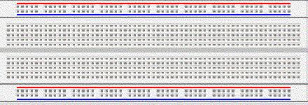
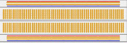
The bread board has many strips of metal (copper usually) which run underneath the board. The metal strips are laid out as shown below.

These strips connect the holes on the top of the board. This makes it easy to connect components together to build circuits. To use the bread board, the legs of components are placed in the holes (the sockets). The holes are made so that they will hold the component in place. Each hole is connected to one of the metal strips running underneath the board.

Each wire forms a node. A node is a point in a circuit where two components are connected. Connections between different components are formed by putting their legs in a common node. On the bread board, a node is the row of holes that are connected by the strip of metal underneath.

The long top and bottom row of holes are usually used for power supply connections.

The rest of the circuit is built by placing components and connecting them together with jumper wires. Then when a path is formed by wires and components from the positive supply node to the negative supply node, we can turn on the power and current flows through the path and the circuit comes alive.

For chips with many legs (ICs), place them in the middle of the board so that half of the legs are on one side of the middle line and half are on the other side.

A completed circuit might look like the following


Want to know more?

Please see videos relating to how to use a breadboard


How to use a breadboard video

PRACTICAL DEFINITIONS OF BASIC COMPONENTS

Resistors


Resistors are components that have a predetermined resistance. Resistance determines how much current will flow through a component. Resistors are used to control voltages and currents. A very high resistance allows very little current to flow. Air has very high resistance. Current almost never flows through air. (Sparks and lightning are brief displays of current flow through air. The light is created as the current burns parts of the air.) A low resistance allows a large amount of current to flow. Metals have very low resistance. That is why wires are made of metal. They allow current to flow from one point to another point without any resistance. Wires are usually covered with rubber or plastic. This keeps the wires from coming in contact with other wires and creating short circuits. High voltage power lines are covered with thick layers of plastic to make them safe, but they become very dangerous when the line breaks and the wire is exposed and is no longer separated from other things by insulation.

Resistance is given in units of ohms. (Ohms are named after Mho Ohms who played with electricity as a young boy in Germany.) Common resistor values are from 100 ohms to 100,000 ohms. Each resistor is marked with colored stripes to indicate it’s resistance.

Variable Resistors


Variable resistors are also common components. They have a dial or a knob that allows you to change the resistance. This is very useful for many situations. Volume controls are variable resistors. When you change the volume you are changing the resistance which changes the current. Making the resistance higher will let less current flow so the volume goes down. Making the resistance lower will let more current flow so the volume goes up. The value of a variable resistor is given as it’s highest resistance value. For example, a 500 ohm variable resistor can have a resistance of anywhere between 0 ohms and 500 ohms. A variable resistor may also be called a potentiometer (pot for short).

Diodes


Diodes are components that allow current to flow in only one direction. They have a positive side (leg) and a negative side. When the voltage on the positive leg is higher than on the negative leg then current flows through the diode (the resistance is very low). When the voltage is lower on the positive leg than on the negative leg then the current does not flow (the resistance is very high). The negative leg of a diode is the one with the line closest to it. It is called the cathode. The postive end is called the anode.

Usually when current is flowing through a diode, the voltage on the positive leg is 0.65 volts higher than on the negative leg.

LED


Light Emitting Diodes are great for projects because they provide visual entertainment. LEDs use a special material which emits light when current flows through it. Unlike light bulbs, LEDs never burn out unless their current limit is passed. A current of 0.02 Amps (20 mA) to 0.04 Amps (40 mA) is a good range for LEDs. They have a positive leg and a negative leg just like regular diodes. To find the positive side of an LED, look for a line in the metal inside the LED. It may be difficult to see the line. This line is closest to the positive side of the LED. Another way of finding the positive side is to find a flat spot on the edge of the LED. This flat spot is on the negative side.

When current is flowing through an LED the voltage on the positive leg is about 1.4 volts higher than the voltage on the negative side. Remember that there is no resistance to limit the current so a resistor must be used in series with the LED to avoid destroying it.

Switches


Switches are devices that create a short circuit or an open circuit depending on the position of the switch. For a light switch, ON means short circuit (current flows through the switch, lights light up and people dance.) When the switch is OFF, that means there is an open circuit (no current flows, lights go out and people settle down. This effect on people is used by some teachers to gain control of loud classes.)

When the switch is ON it looks and acts like a wire. When the switch is OFF there is no connection.

Saturday, October 4, 2008

FRESHER'S BLUES

On the first day of my college I had so many feelings within me,I was excited,nervous,tensed and the list goes on.I was filled with so many questions like,"HOW WILL MY NEW FRIENDS BE?","HOW WILL OUR LECTURER'S BE?","HOW WILL OUR SENIOR'S TREAT US?",etc.,But then I'm so much relieved about all these things.I've made some really good friends not only from my college but also the neighbouring colleges,our lecturer's are also very informative and are also very caring about us.My main fear was about "SENIOR'S",I had always heard pepole saying that the seniors are very mean with their fresher's but in the case of our senior's its not the same.I can affirm that my senior's are very friendly and very much helpful to their fresher's.Its just been a week since our college has started and I'm already in love with it.I'm sure that this college is going to fill my college days full of colour's.........

Warning: Y2K38 Problem Hitting Software World!!!

For all those who are into the IT industry (and those who are not into it too) the Y2K problem would surely ring a bell. There was a situation wherein all computers would be turning their dates and records to zeros during the start of this millennium on the first of January 2000. So,in order to resolve that, large number of mainframe experts were sent to the US and things got settled on time.

However, that has led to another eventuality that might strike and this time the target date is likely to be the month of January and the year is 2038. In common words, once the said date arrives all the computers will reschedule their dates to the year 1901 and what are the consequences of that need not be explained once again. Now, what is causing this situation to arise is the point.

Apparently, when the programs were written to curb the Y2K issue they were done in the C programming language and this uses a standard 4 byte format due to which the beginning of time is recorded as January 1, 1970 at 12:00:00 am and the value for this would be 0.

Also, the signed 4-byte integer has a value of 2,147,483,647 and when the date January 19, 2038 comes it is equivalent to a value of 2,147,483,647 which means that the system will roll onto the negative value. So anyone whose systems are working on the C Programs that use the standard time library will begin to have problems with the date calculations.

While experts are saying that this cannot be deemed as a major threat given the new kind of programs that have emerged, there are those experienced few who cannot guarantee how much of this hypothesis will really work. While that seems to be the challenge for the IT guys to come up with an appropriate solution, the problem would be for the Non IT guys who have made computers their integral part since they would not understand head to tail of the whole algorithm.

All in all, practically speaking there is still a lot of time and given the pace at which the technology is changing, one can be sure that something will surely come up to make things easier but then the evolution of such crises needs to be curbed at any cost since that would mean a lot of laborious work and clean up missions for many employees.