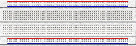
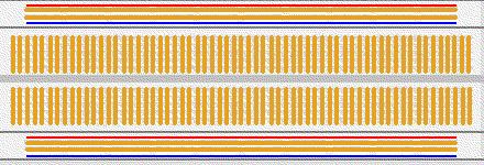
The bread board has many strips of metal (copper usually) which run underneath the board. The metal strips are laid out as shown below.
These strips connect the holes on the top of the board. This makes it easy to connect components together to build circuits. To use the bread board, the legs of components are placed in the holes (the sockets). The holes are made so that they will hold the component in place. Each hole is connected to one of the metal strips running underneath the board.
Each wire forms a node. A node is a point in a circuit where two components are connected. Connections between different components are formed by putting their legs in a common node. On the bread board, a node is the row of holes that are connected by the strip of metal underneath.
The long top and bottom row of holes are usually used for power supply connections.
The rest of the circuit is built by placing components and connecting them together with jumper wires. Then when a path is formed by wires and components from the positive supply node to the negative supply node, we can turn on the power and current flows through the path and the circuit comes alive.
For chips with many legs (ICs), place them in the middle of the board so that half of the legs are on one side of the middle line and half are on the other side.
A completed circuit might look like the following

Want to know more?
Please see videos relating to how to use a breadboard
No comments:
Post a Comment